ESE
Embedded Software Engineering
Technology Overview
Introduction Automatic Identification (Auto ID for short) revolves around the technology
of decoding various machine-readable symbols. This is employed as an alternative
to manual data entry where speed and accuracy are important. The ESE uto-ID
project focuses on basic card technologies providing practical algorithms
that can be used in a variety of embedded applications running on 8, 16,
and 32-bit controllers and processors. Initial algorithms support Barcode
sampling and Barcode decoding for several popular symbologies. Future algorithms
will support Prox (Wiegand), Mag-Stripe, and ISO/IEC 7810, 7816, and 14443
compliant contact and contactless smart cards.
Let me start with an brief overview of some of the alternative data capture
methods to show their strengths and limitations and the applications in
which they're most effective. I won't attempt to cover every contending
technology, rather I'll touch on some of the more prominent ones.
Keyboard Entry
By definition Auto ID is keyless data entry. The keyboard is the
first to go except as an auxiliary input device. As such it is only used
to enter supplementary information and as a backup if the encoded symbol
can't be read.
OCR
Applying electro-optical techniques to machine-readable printed characters,
that are also human-readable, is called optical character recognition (OCR).
OCR is attractive because the same printed characters can be read by people
and machines.
In 1968, American Type Founders produced OCR-A, one of the first optical
character recognition typefaces to meet the criteria set by the U.S. Bureau
of Standards. The result was a font made up of simple, thick strokes to
form recognizable characters that could be deciphered by the computers
of that day and by humans. Using a matrix of photo transducers, the illuminated
symbol is scanned, often using a hand held device. As the scan head travels
across the label, the presence or absence of reflected light indicates
the presence or absence of portions of a character. Once the scan is completed
the acquired optical characteristics are evaluated and the scanned characters
are identified.

Figure 1 - OCR-A Symbols
The National Retail Merchants Association (NRMA) has developed two different
OCR standards. In OCR-A, machine readability is maximized by making each
character as different as possible from each other. Although this helps
with the problem of machine-induced substitution errors, it follows that
the unfamiliar appearance of the OCR-A alphabet results in an increase
in human-induced substitution errors.

Figure 2 - OCR-B Symbols
To make the character set easier on the human eye OCR-B was developed.
It should be evident that OCR-B cannot be machine-read with the same assurance
as OCR-A; machine readability and human readability are, by nature, contradictory.
It's impossible to maximize both human and machine readability using the
same character set.
Figure 3 - MICR E-13B and CMC-7 Symbols
MICR code superficially resembles OCR but is actually composed of magnetic
ink, which embeds the information. MICR readers read the magnetically encoded
symbol using a magnetic read head. The two major MICR fonts are E-13B or
CMC-7. The advantage of MICR is that copied documents do not have the magnetic
ink properties, thus can't be read. MICR is used for monetary checks, passports
and custom printed tickets.
Mag Stripe
Recording data on a magnetic stripe results in a higher bit density that
can easily be realized using a printing process on paper. Magnetics also
offer the capability of altering (rewriting) the recorded data after it's
laid down. Although useful in a number of applications, this may actually
prove a disadvantage in applications where data security is important.
The primary disadvantage of magnetic media is its inability to be inexpensively
printed. Advantages include a relatively high bit density and, for certain
applications, its read/write capability.
Most commonly, magnetic stripes are read by passing an encoded card manually
through a slot reader or by using a mechanized insertion reading device.
Alternately, a hand held wand-like reader can be passed over a stationary
magnetic stripe.

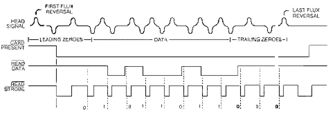
Figure 4 - F2F Data Recovery
The technique of encoding magnetic cards is known as Two-Frequency, Coherent
Phase Recording - generally referred to as F/2F, which allows for the representation
of serial single-channel self-clocking data. Self-clocking is achieved
by combining data bits and clock bits together in a continuous synchronous
sequence. In this scheme an intermediate flux transition signifies a 'one'
bit and the absence of an intermediate flux transition denotes a 'zero'
bit. All modern magnetic stripe read heads contain integrated F/2F bit
recovery circuitry and interface to the processor in a standard fashion
using three wires: card present, clock, and data. These read heads generally
rely on a single integrated circuit to perform the linear signal conditioning,
synchronization, and the recovery of individual bits from the embedded
magnetic flux reversals.
iButton
iButtons, or touch memory, come in a variety of forms. Available in read-only
and read/write configurations, iButton technology can serve applications
that otherwise use card technology.

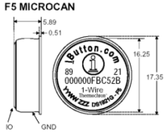
Figure 5 - iButton
The storage media is silicon rather than ink-on-paper or magnetic flux.
This makes for some intriguing possibilities. The fundamental device type
is ROM based and functions as a silicon number tag. Other devices add nonvolatile
RAM to the basic ROM configuration for storing changeable data. This device
category provides numerous variations of both secure and non-secure storage
regions. Finally, these devices can be equipped with a real time clock.
This opens up applications that are unattainable with other technologies.
An iButton reader is easily the least expensive of all the competing technologies.
This is a great deal if your system has a lot of readers and just a few
iButtons. This is seldom the case. Savings at the reader can be offset
by the higher cost of the iButton devices themselves.
The iButton-processor interface consists of a single bidirectional port
pin and a mechanical probe. The probe contacts the iButton's case that
itself resembles a small coin cell (figure 5). The outer shell is the return
connection and the center contact is the data connection. This simple and
rugged case design is one the iButton's principal features since the hermetically
sealed stainless steel case can easily survive such hostile environments
that would quickly turn paper or magnetic stripe tags to pulp.
Bar Code
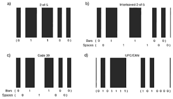
Bar code symbology provides the right feature mix for a lot of data capture
applications such as identifying objects, locations, and people. The first
step in deciphering a bar code involves acquiring the optical bar/space
pattern using some form of electro-optical scanning device.

Figure 6 - Barcodes
Bar code scanners can be hand held or stationary, fully automated or
require an operator, and can operate in the visible or infra-red spectrum.
The least expensive way to scan a bar code label is with a hand held wand
(or light pen). This device contains a built-in light source, and a sensor
for detecting the light reflected from the bar code and. Modern bar code
wands emit a digital representation of the symbol. To do this they come
with all the required amplification and wave shaping circuitry built-in.
Optical slot readers operate essentially on the same principal but require
the bar code to be passed through a slot similar to a magnetic card.
Fixed beam scanners require the bar code to be moved past the scanner.
These can range from very small devices designed to read high density codes
to large units that read containers as they pass on a conveyor belt. Essentially,
these function like non-contact, long range wands.
Moving beam scanners can be hand held or stationary. A number of different
light sources have been used over the years but many modern devices use
laser light to illuminate the symbol. A great depth of field combined with
the rapid, repetitive light sweep results in a much higher "first
read rate" than possible with a single-pass scanner. Ironically this
apparently improved first read rate is really the result of reading the
symbol continuously until it comes out right.
Scanners based on charge coupled device (CCD) arrays can replicate the
function of a moving beam scanner using no moving parts. Basically, using
such a linear array, a solid state scan can be performed by flooding the
symbol with light and reading the transducer array outputs sequentially.
The resulting data stream is accomplished without physical contact or relative
motion between the symbol and the read head.